|
| |
TM 9-2330-398-24
2-63.
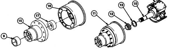
HUB AND BRAKEDRUM ASSEMBLY REPLACEMENT (continued).
NOTE
Wheel bearings and bearing cups are matched sets. If wheel bearings need replacing, bearing
cups must also be replaced.
6.
Inspect inner and outer wheel bearings (12 and 8) for cracks or breaks in bearing cage, etching or pitting on roller
surfaces, and any evidence of wear. Replace if worn or damaged.
7.
Pack inner and outer wheel bearings (8 and 12) from large end of cone with grease, making sure all cavities
between rollers and cage are filled. Cover bearings with clean, lint-free rag until time to install.
8.
Inspect inner and outer bearing cup (17 and 9) in hub (15) for pits, grooves, or flaking. If damaged, use puller to
remove. Drive new bearing cups (9 and 17) into hub (15) with suitable driver.
c.
INSTALLATION
1.
Install hub (15) on brakedrum (16). Install 10 wheel studs, nuts, and lockwashers (para 2-62).
2.
Install inner wheel bearing (12) and seal (13) in hub and brakedrum assembly (11).
3.
Install hub and brakedrum assembly (11) on spindle (10). If hub and brakedrum assembly (11) binds on
brakeshoes (14) when partially installed, adjust brakeshoes (14) to reduce spread (para 2-50d). Push hub and
brakedrum assembly (11) fully onto spindle (10).
4.
Install outer wheel bearing (8) on spindle (10) and in outer wheel bearing cup (9).
5.
Install inner wheel bearing nut (7) on spindle (10) and tighten to minimum of 75 ft-lb. (102 N•m), to ensure proper
seating of wheel bearings (8 and 12) and wheel bearing cups (9 and 16) in hub and brakedrum assembly (11).
6. Loosen inner wheel bearing nut (7) so wheel will turn freely.
7. Tighten inner wheel bearing nut (7) to 50 ft-lb while rotating wheel, in order to properly position bearings for final
adjustment.
WARNING
Failure to back off inner wheel bearing nut could cause overheating of or damage to bearing and
axle spindle. This could cause wheel to lock up or come off during vehicle operation, resulting in
death to personnel or property damage.
8. Loosen inner wheel bearing nut (7) 1/3 turn.
2-154
|