|
| |
TM 9-2330-398-24
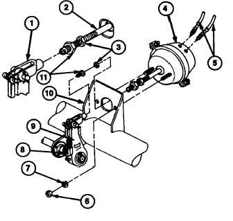
2-51. BRAKE AIR CHAMBER REPLACEMENT AND TEST (continued).
NOTE
Refer to para 2-50 for slack adjuster
adjustment.
2.
Install jamnut (3) approximately 1-5/16 inches
(3.33 cm) from end of push rod (2).
3.
Install yoke adapter (11) on push rod (2)
approximately 3/8 inch (0.95 cm) from end of
push rod (2).
4.
Turn manual adjustment hex (8) clockwise until
yoke adapter (11) extends into bore of yoke (1)
approximately 1/8 inch (0.32 cm). Thread
adapter into yoke and tighten to 10 lb-ft (13.Nn).
5.
Tighten jamnut (3) between 400 and 600 in-ft (45
and 68 N-m).
6.
Connect two brake hoses (5) to brake air
chamber (4).
d.
TEST
1.
Apply and hold a full-pressure brake application.
NOTE
Initial brake application will force out a small amount of air. No air should be
expelled from air chamber after initial application. f air continues to be expelled
from air chamber, replace air chamber.
2.
With prime mover connected and semitrailer brakes applied, coat flanges (12) and connections (14) on brake air
chamber (4) with soapy water.
3.
Inspect flanges (12) and connections (14) for leakage, indicated by bubbles.
NOTE
DO NOT overtighten clamp on brake chamber. Maximum torque should be
between 20 and 25 lb-ft (27.12 and 33.9 Nom). Overtightening will distort flange
and cause more leakage.
4.
If leakage is found at flange (12), tighten clamp (13).
5.
If leakage is found at connections (14), tighten fittings.
FOLLOW-ON MAINTENANCE:
• Disconnect ground (refer to TM 9-2330398-10).
Uncage fail-safe chamber brakes (para 2-60).
2-132
|