|
| |
TM 9-2330-398-24
2-35.
MAIN TRAILER WIRING HARNESS REPLACEMENT (continued).
2.
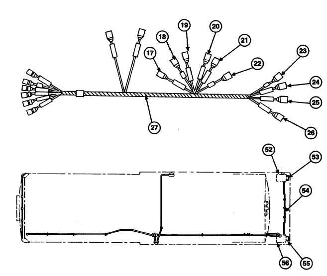
Pull wiring harness (27) through conduit (54) and out through rear curb-side composite light box (52). Disconnect
lacing wire from wiring harness (27).
3.
Install new connectors on each wiring harness lead (para 2-46).
4.
Connect lead 23 connectors (18 and 22) of main trailer wiring harness (27) to lead connectors (49 and 51) of lead
assembly 12275208 (50) inside road-side composite light box (56).
5.
Connect lead 21-489 connectors (19 and 20) of main trailer wiring harness (27) to lead connectors (48 and 46) of
lead assembly 12275205 (47) inside road-side composite light box (56).
6.
Connect lead 24-484 connector (17) and lead 24-461 connector (21) to road-side composite light (55).
7.
Connect lead 21-489 connector (26) 6f main trailer wiring harness (27) to lead 489 connector (45) of lead
assembly 12275204 (44) inside rear curb-side composite light box (52).
8.
Connect lead 23 connector (23), lead 24-483 connector (24), and lead 22-460 connector (25) of main trailer wiring
harness (27) to curb-side composite light (53).
2-91
|