|
| |
TM 9-2330-398-24
2-34.
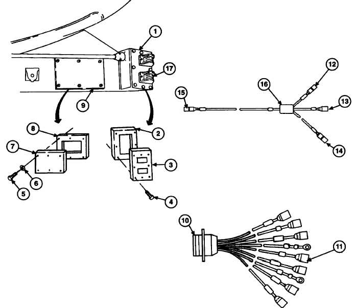
FRONT BLACKOUT MARKER LIGHTS WIRING HARNESS REPLACEMENT (continued).
8.
Connect lead 490 connector (11) of road-side blackout light (17) to lead 490 connector (12) of front blackout
marker lights wiring harness (16).
9.
Connect lead 490 connector (11) of electrical
intervehicular wiring harness lead assembly (10)
to lead 490 connector (13) of front blackout
marker lights wiring harness (16).
10.
Install 16 screws (4) and two cover plates (3) and new gaskets (2) on curb-side and road-side blackout marker
light boxes (1).
11.
Install six screws (5) and new lockwashers (6), access cover (7), and new gasket (8) on semitrailer access hole
(9).
FOLLOW-ON MAINTENANCE:
•
Install roadside composite light cover plate (para 2-30).
•
Disconnect ground (refer to TM 9-2330-398-10).
2-86
|