Order this information in Print

Order this information on CD-ROM

Download in PDF Format


Click here to make tpub.com your Home Page

Page Title: ADJUSTABLE BYPASS VALVE REPLACEMENT
Back | Up | Next

Click here for a printable version

Google


Web
www.tpub.com

Home


Information Categories
.... Administration
Advancement
Aerographer
Automotive
Aviation
Combat
Construction
Diving
Draftsman
Engineering
Electronics
Food and Cooking
Math
Medical
Music
Nuclear Fundamentals
Photography
Religion
USMC
   
Products
  Educational CD-ROM's
Printed Manuals
Downloadable Books


TM   9-2330-272-14 4-102.   ADJUSTABLE   BYPASS   VALVE   REPLACEMENT   (M131A4C   AND   M131A5C). This   Task   Covers: a. Removal b.   Cleaning   and c. Installation Inspection Initial   Setup: Equipment  Conditions: • Tank purged (para 4-64). Tools/Test   Equipment: • General mechanic’s tool kit 
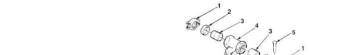
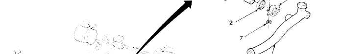
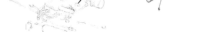
Adjustable bypass valve M131A4C  is  illustrated. a.   REMOVAL Materials/Parts: • Dry cleaning solvent (Item 16, Appendix E) • Two gaskets NOTE is  replaced  the  same  way  on  M131A4C  and  M131A5C. 1. Remove four nuts (7), screws (5), two couplers (1), gaskets (2), and adjustable bypass valve (4) from tubes (6). Discard  gaskets. 2. Remove two nipples (3) from adjustable bypass valve (4). 4-222

Privacy Statement - Press Release - Copyright Information. - Contact Us - Support Integrated Publishing

Integrated Publishing, Inc. - A (SDVOSB) Service Disabled Veteran Owned Small Business