|
| |
TM 9-2330-272-14
4-96. EMERGENCY RELIEF VALVE OPERATOR CONTROL MAINTENANCE.
This Task Covers:
a.
Removal
c.
Adjustment
b. Installation
Initial Setup:
Equipment Conditions:
Materials/Parts:
Tank drained (para 4-64).
Two cotter pins (M131A5 and M131A5C)
Tools/Test Equipment:
Two spring pins
Four cotter pins (M131A4 and M131A4C)
General mechanic’s tool kit
NOTE
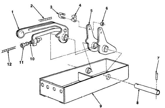
Emergency relief valve operator control is removed the same way on all models except
quantity of control levers vary. M131A5 and M131A5C have two control levers and
M131A4 and M131A4C have four control levers. M131A5 is illustrated.
1.
Remove two nuts (6), U-bolt (3), wire rope (2), and cable clamp (4) from trip assembly (5).
2 .
Remove two nuts (11) and two wire ropes (12) from two adjusting bolts (10).
3.
Remove two spring pins (7) and shaft (8) from trip assembly (5) and two control levers (1). Discard spring pins.
TA702832
4-208
|