|
| |
TM 55-4920-383-13&P
(2)
Set CAPACITANCE RANGE switch (6) to 1000 pF. Check that digital display
reads between 3.5 and 8.5 pF.
(3) Set CAPACITANCE RANGE switch (6) to 4000 pF. Check that digital display
(7) reads between 0 and 16.0 pF.
(4)
Set CAPACITANCE RANGE switch (6) to 8000 pF. Check that digital display (7)
reads between 0 and 26.0 pF.
(5)
Set precision variable capacitor No. 1 to 100.00 pF and set CAPACITANCE
RANGE switch (6) to 200 pF. Check that digital display (7) reads between 99.50 and
100.50 pF.
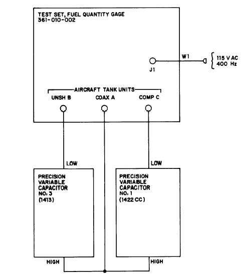
Figure 4-1.
Capacitance measurement and simulation checkout, setup diagram
4-3
|