|
| |
TM 55-2915-335-30&P
2-18. ARMATURE AND FIELD TUBE ASSEMBLY - lNSPECT/REPLACE (Cont)
2-18
4. INSPECTION
a. Inspect Armature
(1)
(2)
(3)
(4)
(5)
(6)
(7)
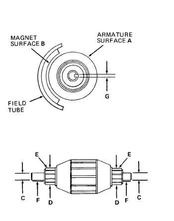
A bent armature shaft will cause armature to
rub on field tube magnets. Check for shiny
spots on armature surface A. Use a flashlight
to check for scoring or loss of material on
field tube magnet surfaces B. If signs of wear
between armature and field tube magnets are
found, replace both armature and field tube.
Using a caliper set, measure diameters C of
armature shaft journals. If either measure-
ment is less than 0.312 inch (7,92 mm) re-
place armature.
Using a caliper set, measure commutator
diameters D. If less than 0.700 inch (17,78
mm) replace armature.
Check roughness of commutator surfaces E.
Run your finger nail lightly over the surface
of each commutator bar. Commutator sur-
face should be smooth with no nicks or
scratches to catch your finger nail. Surface
can be polished to remove any defects by
using 600 grit emery paper moistened with a
light weight oil. After polishing wipe clean
with a lint free cloth moistened in cleaning
solvent (Item 7, Appendix C).
Check commutator surfaces E for pitting. If pitting can not be removed using 600 grit emery paper and
light oil, discard armature.
Shaft surface F should be smooth and free of any scratches and nicks. Polish with 600 grit emery paper and
a lightweight oil. Visually check surface with a light, and spin armature while gently holding the shaft be-
tween your finger tips. Shaft should feel smooth.
Inspect armature keyways if key-drive type is used. Measure keyway width G. Using a feeler gage, take
measurement at outside diameter of shaft. If width G is more than 0.067 inch (1,70 mm), replace both ar-
mature and impeller. The key slot width can also be checked using a No. 50 drill. If the shank of a No. 50
drill can be inserted into the keyway, the keyway is worn.
GO TO NEXT PAGE
2-59
|