|
| |
TM 5-5430-219-13
REMOVAL
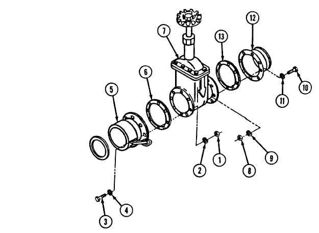
Figure 3-9.
(See figure 3-9.)
Gate Valve
1
2
3
4
Remove hex nuts (1), lockwashers (2), washers (4), and hex-head
capscrews (3).
Remove female quick-disconnect coupling (5) and flange gasket (6) from
face of gate valve (7).
Remove plain hex nuts (8), lockwashers (9), hex-head capscrews (10), and
washers (11), from opposite end of gate valve (7).
Remove male flanged adapter (12) and flange gasket (13) from gate
v a l v e ( 7 ) .
3-20
|