Order this information in Print

Order this information on CD-ROM

Download in PDF Format


Click here to make tpub.com your Home Page

Page Title: TABLE 3-2 TROUBLESHOOTING CONT.
Back | Up | Next

Click here for a printable version

Google


Web
www.tpub.com

Home


Information Categories
.... Administration
Advancement
Aerographer
Automotive
Aviation
Combat
Construction
Diving
Draftsman
Engineering
Electronics
Food and Cooking
Math
Medical
Music
Nuclear Fundamentals
Photography
Religion
USMC
   
Products
  Educational CD-ROM's
Printed Manuals
Downloadable Books


TM   5-5430-219-13 
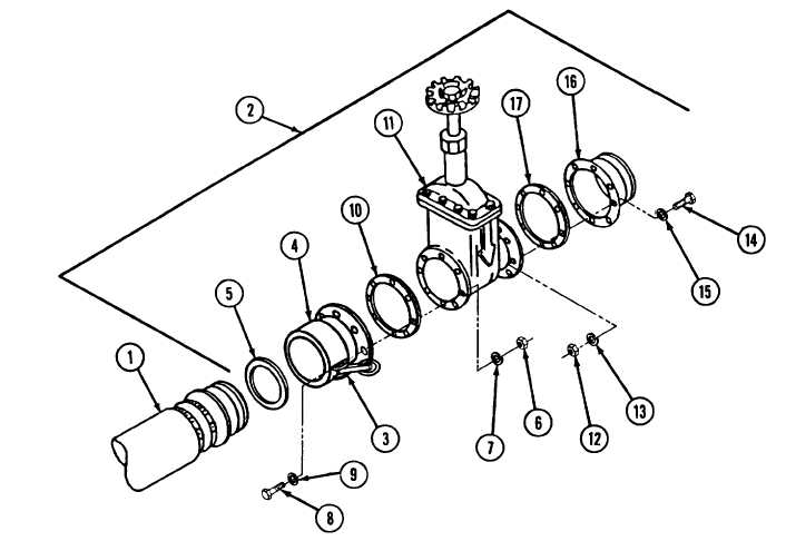
REMOVAL   (See   figure   3-8.) Disconnect   hose   assembly   (1)   from   gate   valve   assembly   (2). a . Pull   cam-lever   arms   (3)   outward   on   female   quick-disconnect coupling    (4). b. Withdraw   hose   assembly   (1). DISASSEMBLY  (See  figure  3-8.) 1   Remove   coupling   gasket   (5)   from   inside   of   quick-disconnect   coupling   (4) on   gate   valve   assembly   (2). 2   Remove   hex   nuts   (6),   lockwashers   (7),   hex-head   capscrews   (8),   and washers   (9). 3   Remove   female   quick-disconnect   coupling   (4)   and   flange   gasket   (10)   from face   of   gate   valve   (11). 3-17 Figure   3-8   Filler   and   Discharge   Valve   Assembly

Privacy Statement - Press Release - Copyright Information. - Contact Us - Support Integrated Publishing

Integrated Publishing, Inc. - A (SDVOSB) Service Disabled Veteran Owned Small Business