|
| |
TM 5-5430-219-13
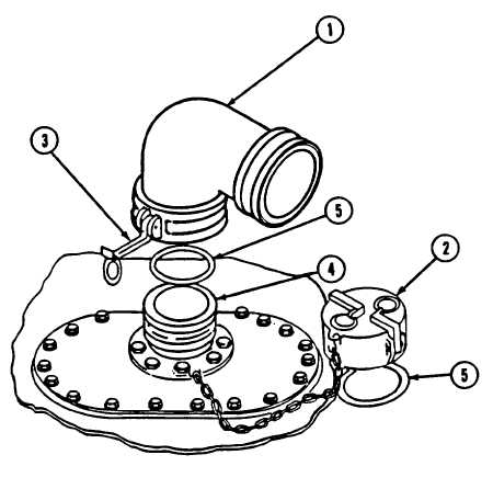
Figure 2-17.
Filler/Discharge Assembly
DISASSEMBLY (See figure 2-17. )
1 Remove 4 in. elbow (1) or dust cap (2) by pulling outward on cam-lever
arms (3).
Lift elbow or dust cap from flanged adapter (4).
2 Remove gasket (5) from inside elbow (1) or dust cap (2).
ASSEMBLY (See figure 2-17.)
1 Place new gasket (5) in dust cap (2) or elbow (1).
2 Place elbow (1) or dust cap (2) on flanged adapter (4). Pull inward on
cam-lever arms (3) to lock items together.
2-29
|