Order this information in Print

Order this information on CD-ROM

Download in PDF Format


Click here to make tpub.com your Home Page

Page Title: Figure 2-15. Drain Hose Assembly\
Back | Up | Next

Click here for a printable version

Google


Web
www.tpub.com

Home


Information Categories
.... Administration
Advancement
Aerographer
Automotive
Aviation
Combat
Construction
Diving
Draftsman
Engineering
Electronics
Food and Cooking
Math
Medical
Music
Nuclear Fundamentals
Photography
Religion
USMC
   
Products
  Educational CD-ROM's
Printed Manuals
Downloadable Books


TM 3. 4. 5-5430-219-13 
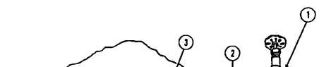
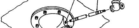
Remove filler and discharge hose (3). Remove hose coupling gasket (4) if damaged. INSTALLATION (See figure 2-14.) 1.  Install  new  hose  coupling  gasket  (4)  in  female   quick-disconnect coupling (5) on filler and discharge hose (3). 2.  Connect  filler  and  discharge  hose  (3) 3.  Push  in  cam-lever  arms  (2)  to  locked to gate or butterfly valve (1) assembly. position on gate or butterfly valve (1) assembly. 2-15.  MAINTENANCE  OR  DRAIN  HOSE  ASSEMBLY. This  task  covers: a.   Removal b.   Installation INITIAL SETUP Tools General Mechanic’s Automotive Tool Kit, SC 5180-90-CL-N26, NSN 5180-00-177-7033 Materials/Parts Sealing compound, item 2, appendix E Figure 2-15. Drain Hose Assembly 2-26  Change  2

Privacy Statement - Press Release - Copyright Information. - Contact Us - Support Integrated Publishing

Integrated Publishing, Inc. - A (SDVOSB) Service Disabled Veteran Owned Small Business