|
| |
TM 5-5430-219-13
ASSEMBLY (See figure 2-13)
1. Install coupling gasket (5), if damaged, on inside of female quick-disconnect coupling (4).
2. Connect hose assembly (1) to filler and discharge valve assembly (2).
a. Install hose assembly (1) on filler and discharge valve assembly (2).
b. Push in cam-lever arms (3) on female quick-disconnect coupling (4).
2-14 MAINTENANCE OF FILLER AND DISCHARGE HOSE ASSEMBLY.
This task covers:
a. Removal
b. Repair*
c. Installation
*Repair is limited to quick-disconnect gasket replacement which is included in removal and installation
steps.
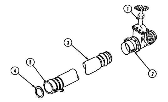
Figure 2-14. Filler and Discharge Hose Assembly
NOTE
The filler and discharge hose is fitted with a female quick-disconnect coupling on
one end and a quick-disconnect male adapter on the other end.
REMOVAL (See figure 2-14)
1. Be sure gate, butterfly, or ball valve (1) is closed.
2. Release cam-lever arms (2) from locked position on filler and discharge hose (3) end.
Change 4 2-25
|