|
| |
TM 5-5420-219-13
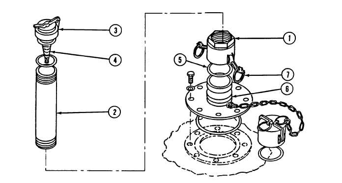
Figure 2-8.
Vent and Pipe Assembly
c .
Inspect female coupling half (1) and vent pipe (2) for cleanliness.
(See figure 2-8. )
NOTE
Normally the vent pipe and female coupling half will be received
preassembled.
d .
Check to see that relief cap (3) operates freely.
e .
Check to see that flame arrestor (4) is installed.
f .
Check to see that relief cap (3) is installed tightly on vent
p i p e ( 2 ) .
g.
Check to see that gasket (5) is in place and correctly seated.
h.
Insert female coupling half (1) over flanged adapter (6) with
cam-lever arms (7) in outward position.
i .
Press cam-lever arms (7) upward and inward to lock vent pipe
assembly into operating position.
2-16
|