|
| |
TM 5-5430-210-12
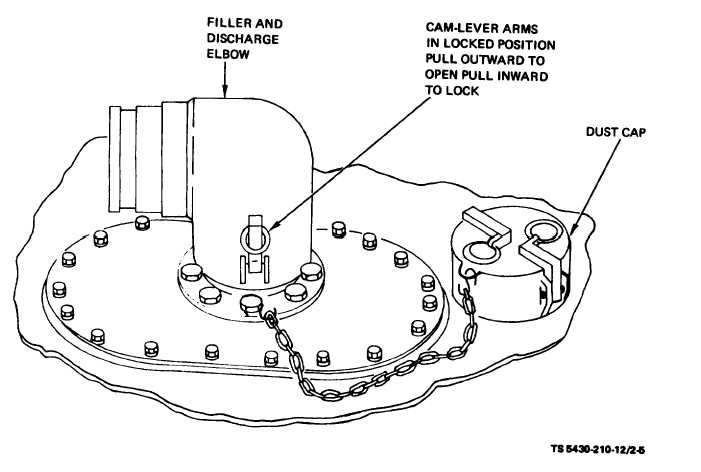
(2) Inspect the filler and discharge elbows for
c. Installation of Drain Assembly Plug and
cleanliness and to see that the gaskets are in place
Drain Hose Assembly (Excluding Tank, NSN 5430-
and are properly seated.
00-268-8187).
(3) Position the female end of the filler and
(1) Fold the tank back to expose the drain as-
discharge elbow over the filler and discharge
sembly and remove the drain plug (fig. 2-6).
adapter with the cam-levers in the outward posi-
(2) Apply pipe joint compound or teflon tape
tion. Turn the elbow so that the open end points to
the nearest end of the tank. Lift the cam-levers and
to the threads of the drain hose fittings and install
lock the elbow in place. Install the dust cap on the
in the drain assembly (fig. 2-7).
(3) Install the 1/2-inch (1.27-centimeter) con-
open end of the elbow and lock in place (fig. 2-5).
trol valve on the end of the drain hose. (fig. 2-7)
Figure 2-5.
Filler and Discharge Elbow, All Tanks.
2-6
|