Order this information in Print

Order this information on CD-ROM

Download in PDF Format


Click here to make tpub.com your Home Page

Page Title: Figure 2-4. Filler and Discharge Dust Cap, All Tanks
Back | Up | Next

Click here for a printable version

Google


Web
www.tpub.com

Home


Information Categories
.... Administration
Advancement
Aerographer
Automotive
Aviation
Combat
Construction
Diving
Draftsman
Engineering
Electronics
Food and Cooking
Math
Medical
Music
Nuclear Fundamentals
Photography
Religion
USMC
   
Products
  Educational CD-ROM's
Printed Manuals
Downloadable Books


TM 5-5430-210-12 (3) Check to see that the pressure relief valve into operating position. is screwed tightly on the vent pipe. b. Installation of Filler and Discharge Elbow As- (4)  Attach  the  vent  pipe  assembly  to  the  2- semblies. inch (5.08-centimeter) flanged adapter by inserting 
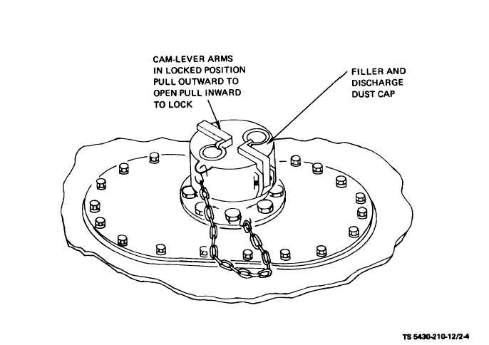
(1) Remove dust cap (fig. 2-4) from filler and its female end (with cam-lever arms in the outward discharge  adapter  by  pulling  the  cam-lever  arms position) over the male cam-lock end of the flanged outward and lifting upward on the dust cap. (Dust adapter  and  pressing  upward  and  inward  on  the cap is chain attached to prevent loss.) cam-lever arms which lock the vent pipe assembly Figure 2-4. Filler and Discharge Dust Cap, All Tanks. 2-5

Privacy Statement - Press Release - Copyright Information. - Contact Us - Support Integrated Publishing

Integrated Publishing, Inc. - A (SDVOSB) Service Disabled Veteran Owned Small Business