|
| |
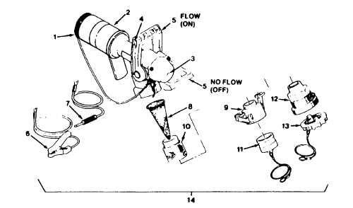
TM5-4930-235-13&P
Key
Control or Indicator
Function
1
Outlet Cap Assembly
Keeps dirt and contaminants out of nozzle.
2
Pullback Sleeve
Pulls back toward handle to release outlet cap or to attach nozzle to
aircraft receptacle.
3
Indicator Shaft
Extends from nozzle assembly to indicate full fuel tank. Retracts to
indicate flow.
4
Thumb Latch
Locks handle in FLOW (on) or no flow (off) position. Press to move
handle; release to lock handle.
5
Handle
Controls flow of fuel. Push forward for FLOW (on). Pull back for no flow
(off).
6
Ground Clip Assembly
Clamps to grounding rod near aircraft before connecting nozzle body.
Prevents static electric shock, fire hazards.
7
Ground Plug Assembly
Connects to aircraft before connecting nozzle assembly. Prevents static
electric shock, fire hazards.
8
Strainer
Prevents damage to nozzle assembly and/or aircraft by removing dirt.
9
Coupling Half
Connects nozzle assembly to fuel hose or dust plug. Pull cam arms
outward from coupling half to install. Push cam arms inward towards
coupling half to lock.
10
Strainer Body
Must be removed to access strainer.
11
Dust Plug
Keeps dirt and contaminants out of nozzle assembly.
12
Coupling (Unisex)
Connects nozzle assembly to fuel hose or dust plug. Insert lugs in slots on
fuel hose coupling, turn clockwise to lock.
13
Dust Cap (Used with model
125-0505 only)
Keeps dirt and foreign material out of the nozzle body. To install, insert in
unisex coupler (12) and turn clockwise.
14
Nozzle Assembly
Internally regulates flow of fuel. Has a vacuum break valve in outlet end.
Figure 2-1. Operator's Controls and Indicators
(Model Numbers 125-10000 and 125-0505).
Change 1
2-2
|