|
| |
TM 5-4930-234-13&P
24.
Lightly lubricate o-ring (12). Install in groove of piston (14).
25.
Lightly lubricate o-ring (8). Install in groove of bonded guide (7).
26.
Lightly lubricate check valve (9). Insert pointed end through hole in bonded guide (7). Use a pair of needle nose
pliers inside bonded guide to pull on pointed end of check valve (9) until it snaps in place.
27.
Install piston (14) in bonded guide (7). Push on rack (10) until piston (14) stops in bonded guide (7).
28.
Install bonded guide (7) in body (49) with rack (10) pointing up. Three holes in bonded guide (7) must be aligned
with three holes in body (49).
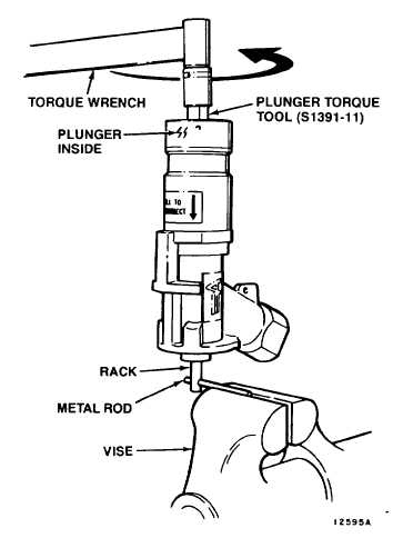
29.
Remove body (49) from vise. Insert a metal rod through hole in rack (10) and clamp metal rod in vise. See Figure
5-19. Nose sleeve (38) on body (49) should point up.
30.
Install safety sleeve spring (3) in safety sleeve (2). Insert plunger (1) through safety sleeve (2). Install parts in
body (49).
Figure 5-19. Plunger Assembly
5-24
|