|
| |
TM 5-4930-234-13&P
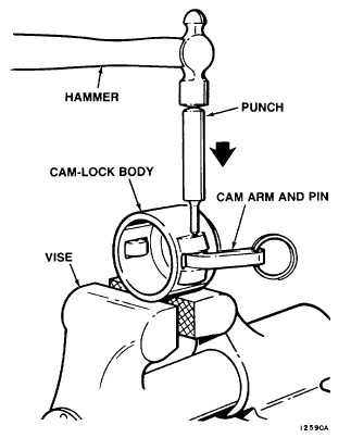
NOTE
One side of pin has a recessed hole. Cam-lock stake tool goes in this hole.
4.
Stake pin in cam-lock body using cam-lock stake tool, S1391-3, and hammer.
5.
Remove cam-lock stake tool.
6.
Turn cam-lock body to position other side on dowel pin in cam-lock stake plate, S1391-5. Repeat steps
2 thru 5.
7.
Remove cam-lock body from cam-lock stake plate.
f.
Installation (See Figure 5-1).
1.
Install cam-lock coupling (4) in nozzle (1) and turn clockwise until hand-tight.
2.
Insert dust plug (3) in end of cam-lock coupling (4).
3.
Pull cam arms (2) toward nozzle (1) to lock in place.
Figure 5-2. Cam Arm Disassembly
Figure 5-3. Cam Arm Assembly
5-7
|