|
| |
TM 5-4930-226-12&P
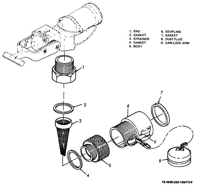
Figure 3-2. Strainer assembly - exploded view.
b. The following procedures apply to strainer as-
for damage, replace as required.
semblies in serial number range 0001 thru 0470.
(4) Reassembly.
(1) Removal. Remove strainer assembly (fig.
(a) Place gasket (6) in coupling (5).
3-3) from nozzle assembly.
(b) Replace end (1) in nozzle assembly. Re-
(2) Disassembly.
place O-ring (2) in end (l).
(a) Open cam-lock keeper and remove dust
(c) Place body (4) and coupling (5) over
plug (7, fig. 3-3).
strainer (3) and screw into end (1). Hand tighten
(b) Unscrew body (4) from end (1) remove
only.
strainer (3) and O-ring (2) from end (1).
(d) Replace dust plug (7) on coupling (5).
(c) Remove gasket (6) from coupling (5).
NOTE
(d) Unscrew coupling (5) from body (4) if
Repair of the strainer assembly is limited to re-
damaged or leaking.
placement of faulty parts.
(3) Inspection. Inspect O-ring and strainer
3-8
|