|
| |
TM 5-4320-313-14
5-10.
CYLINDER- Continued.
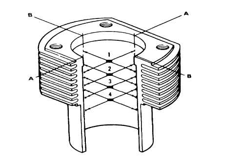
c. Inspection. (Refer to figure 5-25).
(1) Measure cylinder bore at levels 1 to 4 of engine centerline axis A and crossline axis B. A normal or new
bore diameter should be 2.8740 to 2.8774 inches (73.00 to 73.09 mm). If wear limits for a normal bore
cylinder have been reached or exceeded, replace cylinder and piston. If measurements on axis A and axis
B are different, cylinder is out of-round or has high spots. Replace cylinder.
(2) Check that the top and bottom joint faces are smooth and flat. If damaged, replace cylinder.
Figure 5-25. Cylinder Measuring Points.
d. Installation. (Refer to figure 5-26).
(1) Check that piston rings are offset by 120 degrees.
(2) Compress piston rings with piston ring clamp (1).
CAUTION
Use care when installing cylinder to prevent damage to piston rings.
NOTE
Recessed part of cylinder must be to front of engine.
5-38
|