Order this information in Print

Order this information on CD-ROM

Download in PDF Format


Click here to make tpub.com your Home Page

Page Title: CYLINDER HEAD AND VALVE ASSEMBLY - Continued
Back | Up | Next

Click here for a printable version

Google


Web
www.tpub.com

Home


Information Categories
.... Administration
Advancement
Aerographer
Automotive
Aviation
Combat
Construction
Diving
Draftsman
Engineering
Electronics
Food and Cooking
Math
Medical
Music
Nuclear Fundamentals
Photography
Religion
USMC
   
Products
  Educational CD-ROM's
Printed Manuals
Downloadable Books


TM 5-4320-313-14 CAUTION Do not scratch the cylinder head sealing face.  Scratches could cause poor sealing of cylinder head and cylinder. 
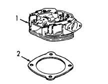
(8) Refer to figure 5-19 and remove cylinder head (1) and gasket (2). Discard gasket. Figure 5-19.  Cylinder Head Removal. 
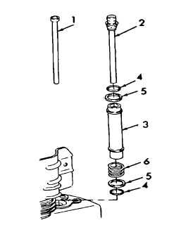
(9) Refer to figure 5-20 and remove pushrod (1) and pushrod (2) from protection tubes (3). (10)Remove protection tubes (3), packings (4), shims (5), and springs (6).  Discard packings (4). NOTE Complete pushrod (2) belongs to injection pump side of engine. Figure 5-20.  Pushrods and Protection Tube Removal. 5-31

Privacy Statement - Press Release - Copyright Information. - Contact Us - Support Integrated Publishing

Integrated Publishing, Inc. - A (SDVOSB) Service Disabled Veteran Owned Small Business