|
| |
TM 5-4320-313-14
5-5. ENGINE ASSEMBLY- Continued.
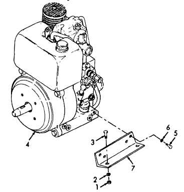
a. Removal. (Refer to figure 5-3).
(1) Remove four nuts (1), four lockwashers (2), and four screws (3).
Engine weighs 75 lbs (34 kgs). Two persons are required to lift engine. Failure to observe this warning
can result in injury to personnel.
(2) Slowly raise engine and remove engine assembly (4). Set engine assembly on wooden blocks to prevent damage
to bottom of engine.
(3) Remove eight screws (5), eight lockwashers (6), and two brackets (7).
b. Installation.
(1) Install two brackets (7) and secure with eight lockwashers (6) and eight screws (5).
(2) Slowly raise engine assembly (4) and place in base. Carefully lower engine assembly (4) and aline mounting holes.
(3) Install four screws (3), four lockwashers (2), and four nuts (1).
Tighten nuts securely.
Figure 5-3. Engine Assembly Removal/Installation.
5-10
*U.S. GOVERNMENT PRININNG OFFICE: 1"2 - 755-0OZ8/6S1
|