Order this information in Print

Order this information on CD-ROM

Download in PDF Format


Click here to make tpub.com your Home Page

Page Title: AIR FILTER INDICATOR
Back | Up | Next

Click here for a printable version

Google


Web
www.tpub.com

Home


Information Categories
.... Administration
Advancement
Aerographer
Automotive
Aviation
Combat
Construction
Diving
Draftsman
Engineering
Electronics
Food and Cooking
Math
Medical
Music
Nuclear Fundamentals
Photography
Religion
USMC
   
Products
  Educational CD-ROM's
Printed Manuals
Downloadable Books


TM 5-4320-313-14 4-11.   AIR FILTER INDICATOR. This task consists of: a.    Removal b.    Installation INITIAL SETUP: Tools Required: Tool Kit, General Mechanics (item 1, appendix B) Materials Required: Gasket, P/N 03477200 Equipment Conditions: Pumping assembly shut down in accordance with paragraph 2-6. 
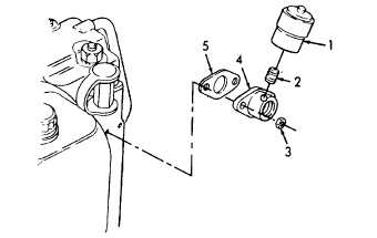
a. Removal.  (Refer to figure 4-3). (1) Unscrew air filter indicator (1) from nipple (2). (2) Remove nipple (2). (3) Remove two nuts (3), adapter (4), and gasket (5).  Discard gasket (5). b. Installation. (1) Install new gasket (5), adapter (4), and secure with two nuts (3). (2) Install nipple (2). (3) Position air filter indicator (1) on nipple (2) and hand tighten. Figure 4-3.  Air Filter Indicator Removal/Installation. 4-11

Privacy Statement - Press Release - Copyright Information. - Contact Us - Support Integrated Publishing

Integrated Publishing, Inc. - A (SDVOSB) Service Disabled Veteran Owned Small Business