|
| |
TM 5-4320-313-14
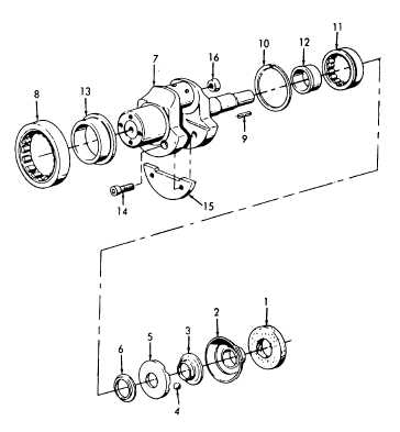
(7) Using an oven, heat crankcase to 175° to 210°F (80° to 100°C).
(8) Install crankshaft (7) into crankcase until mounting device stops. Allow crankcase to cool and remove
mounting device. Install key (9)
WARNING
Wear asbestos gloves to avoid serious burns when handling heated parts.
NOTE
Do not disturb position of crankshaft end play when installing the following.
(9) Using an oven heat ball hub disc (3), ball hub (5), and spacer (6) to 160° to 175°F (70° to 80°C).
(10) Install spacer (6), ball hub (5), and ball hub disc (3) onto crankshaft using ball hub impact mandrel.
(11) Apply grease to four balls (4) and install in hub (5) one in every other notch.
(12) Install shell (2) and disc (1) on crankshaft.
(13) Refer to paragraph 6-5 and install oil seal (flywheel side).
(14) Refer to paragraph 6-3 and install timing cover and camshaft.
(15) Refer to paragraph 6-2 and install connecting rod.
(16) Refer to paragraph 6-4 and install governor.
Figure 6-13. Crankshaft Installation.
6-23
|