|
| |
TM 5-4320-313-14
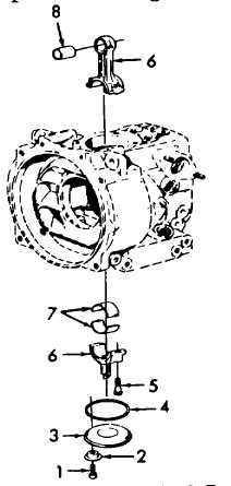
a. Removal.(Refer to figure 6-4).
NOTE
Remove oil fill plug. Insert a screwdriver through oil fill hole and push out cover (3).
(1) Remove four screws (1), four caps (2), cover (3), and packing (4). Discard packing (4).
CAUTION
When removing connecting rod, make sure it does not knock against crankcase. This could result in
serious damage to connecting rod.
(2) Using allen socket, remove two allen screws (5) and remove bottom half of connecting rod (6).
(3) Remove top half of connecting rod (6) from top of crankcase.
(4) Remove two bearing halves (7) from both halves of connecting rod (6).
(5) Refer to figure 6-5 and measure the inside diameter of connecting rod bushing. Measure at points 1 and 2
along axes A and B. Measurements should be .9858 to .9877 inch (25.040 to 25.073 mm). If measurement
is over .9877 inch (25.088 mm) limit, replace rod bushing.
(6) Using a arbor press, Dress bushing (8) from connecting rod (7).
Figure 6-4. Connecting Rod Removal.
6-7
|