|
| |
TM 5-4320-308-13
2-2. OPERATING PROCEDURE (Continued)
(4)
If pump is to be removed from system, remove pipe plug (1) and drain pump.
(5)
Remove suction hose from suction (intake) female coupling (2).
(6)
Remove discharge hose from discharge male coupling (3).
(7)
Cover suction (intake) female coupling (2) with dust plug (4).
(8)
Cover discharge male coupling (3) with dust cap (5).
(9)
Turn 3-way valve handle (6) counterclockwise to OFF position.'
2-3. IDENTIFICATION AND CAUTION PLATES
The pumping assembly has the following identification and instruction plates.
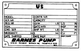
a.
Identification plate. Located on the storage container.
Provides the pump identification number, serial number,
dimensions, weight, and shipping information.
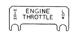
b.
Throttle plate. Located on top of gear housing. Indicates
throttle lever position for high and low engine speed.
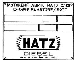
c.
Engine nameplate. Located on the flywheel end, left side
of the engine. Provides engine identification.
2-10
|