|
| |
TM 5-4320-308-13
4-17.
INSPECT/REPLACE CYLINDER HEAD AND VALVE ASSEMBLY (Continued)
i.
Subtract reading on dial gage that was recorded from the required clearance of 0.0217/0.0256 inch (0.55/0.65
mm). This difference is the thickness of the gasket needed for proper cylinder head clearance.
NOTE
Gaskets come in various thicknesses. If you have a choice between two gaskets, it is best to use
the thickest one.
j.
Remove dial gage 612 087 00 with measuring device 603 114 00, and retaining bracket 612 752 00.
2
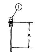
Adjust complete pushrod (1) so dimension A equals 5. 8189/5. 8268
inches (147. 8/148. 0 mm). This adjustment is required for proper
engagement of complete pushrod with pinion on decompression shaft.
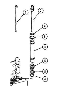
3
Install preformed packings (4), shims (5), pressure
springs (6), and protection tubes (3).
4
Install complete pushrod (2) closest to injection pump
side of engine.
5
Install pushrod (1).
4-44
|