|
| |
TM 5-4320-308-13
4-15. TEST/REPLACE/ADJUST INJECTION PUMP (Continued)
WARNING
Death or serious injury could occur if fuel is not handled carefully. Use in a well-ventilated area
away from open flame, arcing equipment, ignition sources, heaters, or excessive heat. Always
store fuel in proper, marked containers.
DO NOT SMOKE.
Death or serious injury could occur if compressed air is directed against the skin. Do not use
compressed air for cleaning or drying unless the pressure is/has been reduced to 30 psi (2.06 bar)
or less. When working with compressed air always use chip guards, eye protection, and other
personal protective equipment.
4
Clean all parts with clean diesel fuel and dry with low-pressure compressed air.
5
Inspect mating surface of injection pump for roughness or other damage. Scratches or other damage may result in
pressure leaks. Check for wear at contact areas. Replace injection pump if worn.
INSTALLATION:
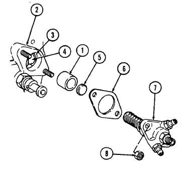
1
Install tappet (1) into crankcase (2).
2
Turn engine by hand until tappet (1)
reaches the lowest point of cam (3).
3
Position throttle control hand lever so that
governor lever slot (4) lies exactly in the
center of the tappet bore.
4.
Install plate (5), with the flat surface
toward the injection pump (7).
5
Place shim pack (6) on crankcase (2)
studs.
6
Position control sleeve on injection pump
(7) so that control sleeve pin enters slot in
governor lever.
7
Insert injection pump (7) carefully without
moving the control sleeve out of its roper
position.
NOTE
No resistance should be felt until the pump is within 0.160 inch (4 mm) of the crankcase, then a
resistance due to initial load of plunger spring can be felt.
CAUTION
Do not tighten pump if not seated properly. Damage to pump, governor lever, or engine could
result if improperly installed.
8
Using hand pressure, insert injection pump (7) fully into crankcase (2) and install two hexagon nuts (8). If the
pump does not seat properly, governor sleeve pin of injection pump has not entered slot (4) in governor lever.
4-29
|