|
| |
TM 5-4320-308-13
3-30. ADJUST CYLINDER HEAD AND VALVE ASSEMBLY (Continued)
7
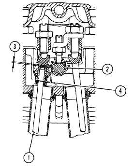
Check clearance of complete pushrod (1) and
pinion (2).
a.
Use a feeler gage to check that clearance
(3) between socket of complete pushrod
(1) and pinion (2) is 0.039 inch (1.0 mm).
b.
Check that clearance (4) is 0. 039 inch (1.
0 mm).
c.
Clearances can be adjusted by adjusting
complete pushrod (1) for clearance (3),
and adjusting rocker shaft for clearance
(4).
NOTE
During
engine
operation
decompression shaft must not move.
Assured
clearances
will
prevent
movement.
8
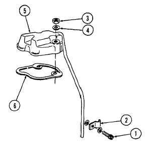
Install new gasket (6) on cylinder head.
9
Install cylinder head cover (5) on gasket (6).
10
Install two spring washers (4) and nuts (3).
Tighten securely.
NOTE
Insure
that
copper
washers
are
installed on both sides of the pipe clip
to prevent oil leaks.
11
Install pipe clip (2) and screw (1).
3-71
|