|
| |
TM 5-4320-306-24
2-16. REPLACE/REPAIR CONTROL PANEL ASSEMBLY (Continued)
1
Place left side of throttle panel (37) in left opening of control panel (4) with right side of throttle panel angled out
60 degrees toward front of unit.
2
Connect two fluid hoses (38) at quick disconnects (39).
3
Position the right side of the throttle panel (37) in control panel (4) and fasten wing nut (36) on right side of
throttle panel.
4
Install throttle knob and vernier (40) through front of throttle panel (37).
5
Connect and lock throttle control cable (41 ) at quick release (42) on back of throttle panel.
6
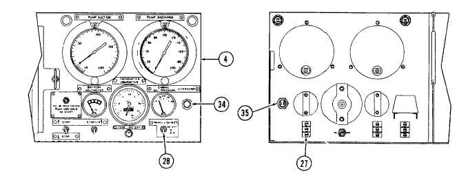
Install charging indicator lamp (ALTERNATOR) (34) through front of control panel (4).
7
Install nut (35) at back of indicator lamp (34).
8
Attach two tagged wires.
9
Install PANEL LIGHTS switch (27) through back of control panel (4).
10
Install nut and spring lockwasher (28) on PANEL LIGHTS switch (27).
11
Attach six tagged wires to PANEL LIGHTS switch (27) with three screws.
2-59
|