|
| |
TM 5-4320-306-24
2-16. REPLACE/REPAIR CONTROL PANEL ASSEMBLY (Continued)
40
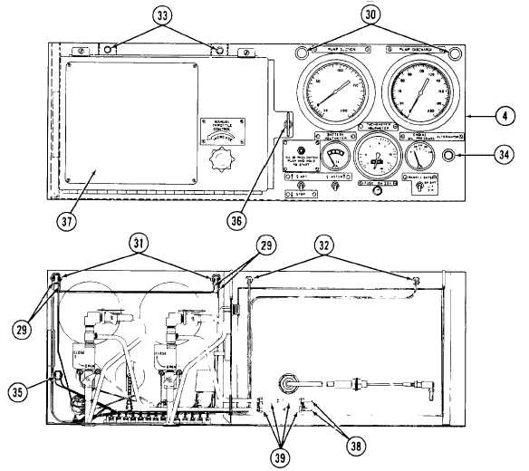
Tag seven wires (29) on panel lights (30). Remove four screws and seven wires (29) from panel lights (30).
41
Remove knurled nut (31) from back of light fixtures.
42
Remove panel lights (30) from front of control panel (4).
43
Tag and remove four wires (32) from panel lights (33).
44
Pull panel lights (33) from front of control panel (4).
45
Tag and remove two wires from charging indicator lamp (ALTERNATOR) (34)
46
Remove nut (35) from back of indicator lamp (34).
47
Remove charging indicator lamp (34) through front of control panel (4).
48
With extreme care, release wing nut (36) on right side of throttle panel (37). Hinge out throttle panel 60 degrees
toward front of unit.
49
Disconnect two fluid hoses (38) at quick disconnects (39).
50
Remove throttle panel (37) from front of control panel (4).
2-57
|