|
| |
TM 5-4320-306-24
4-11
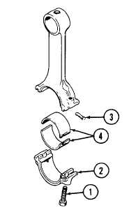
REPLACE/REPAIR CONNECTING ROD ASSEMBLY (Continued)
13
Remove big-end bolts (1), bearing cap (2), and dowel pin (3), and carefully insert bearing shells (4) Reinsert pin
and tighten big-end bolts following procedure described in step 9 above.
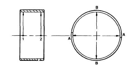
14
Check bearing shell bore
a
Measure with inside micrometer at points 1 and 2 and along axes A and B. Measurement should be 2
5209 to 2.5224 inches (64.031 to 64.069 mm).
b.
If any measurement is outside the tolerance limits, replace the bearing shells.
c
Make sure that measurements at points 1 and 2 are not different nor outside the tolerance limits indicating
that bearing shell is wearing in a conical shape.
d
Make sure measurements along axes A and B are not different nor outside the tolerance limits indicating
bearing shell is wearing in an oval shape.
e
If bearing shell is wearing out-of-round, replace it and check the crankpin on the crankshaft. Follow
procedure described in paragraph 4-12 Also check pistons and cylinders for unusual wear. Follow
procedures described in paragraphs 4-9 and 4-10.
4-87
|