|
| |
TM 5-4320-306-24
4-4. REPAIR INJECTION PUMP (Continued)
5
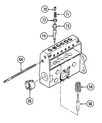
Inspect six pistons (56) and six plungers (74) for
scratches, nicks, and grooves. Dip each mating plunger
and barrel in clean calibrating fluid. Place piston in
plunger Hold parts vertically and position about 3/4 of
plunger length in piston Release plunger into barrel.
Plunger must slide smoothly into barrel until it reaches
the stop If part fails inspection replace mating barrel and
plunger as an assembly.
6
Inspect six delivery valves (73) and six fillers (70) for
cracks or grooving. Inspect delivery valve for crushed or
unevenly worn seats. Insert each filler into mating
delivery valve and inspect for freedom of movement If
either part is damaged, replace both filler and its mating
delivery valve.
7
Inspect six piston springs (58) for damage to protective
coating, cracks, or permanent set Replace damaged
spring
8
Inspect rod (64) for chipping, cracks, or worn gear teeth
Remove slight grooving using crocus cloth If otherwise
damaged, replace rod.
9
Inspect flyweight (26) for damaged or worn rollers,
pivot pins, and weights. If damaged, replace flyweight as
an assembly.
10 Inspect all other parts for cracks, distortion, uneven wear, or heavy grooving Inspect all threaded parts for damage to
threads. Replace damaged part
ASSEMBLY:
1
Install two rings (79) into housing.
2
Install threaded ring (78).
3
Install guide bushing (77) using ring wrench KDEP 2961.
4
If new rings (79) were installed, ream rings using bushing reamer KDEP 2999 Remove all chips created by reaming
operation.
5
Place together the following parts tagged as belonging to bore number one during disassembly. pipe connection
(68), filler (70), spring (71), delivery valve (73), and plunger (74). Install parts as follows
a.
Lower plunger (74) into housing bore number one Aline groove in plunger with pin in housing.
b.
Install delivery valve (73) into bore and onto plunger.
c.
nstall a new sealing washer (72)
4-17
|