|
| |
TM 5-4320-306-24
3-6. REPLACE ENGINE ASSEMBLY (Continued)
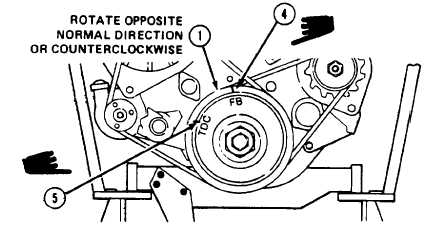
17 Rotate V-belt pulley (1) counterclockwise until the FB mark (4) is approximately 90 degrees before engine TDC (5).
18 Rotate V-belt pulley (1) clockwise until the FB mark (4) aligns with the timing pin on the cover above the pulley. The
crankshaft, gearing, and valves are in position for beginning of fuel delivery. Hold the crankshaft V-belt pulley in this
position until the injection pump is adjusted. Paragraph 3-21 gives instructions for removal of idler pulley assembly for
access to the injection pump adjustment.
NOTE
Parts or tools should be protected from dropping Into the front cover using a
shop cloth.
19. Loosen hex bolts (1) but do not
remove them from injection pump
gear (2) and hub (3). The drive hub
cap can now be turned without gear
movement.
20. Slowly rotate injection pump hub (3)
and shaft clockwise until the injection
pump starts to deliver fuel. If
necessary, rotate injection pump hub
fully counterclockwise, and repeat
this step.
21. Pump high pressure timing device
No. 0030714 until fuel comes out of
stub pipe at 5 to 8 second intervals.
When it does, the injection pump is
adjusted for beginning of fuel
delivery.
22. Without changing the position of in-
jection pump gears (2) or hub (3),
tighten the hex bolts (1) that secure the injection pump hub to the injection pump gear.
23. Recheck fuel injection timing and adjust if necessary. To readjust, repeat procedure starting with step 12. If no
adjustment is necessary, fuel injection timing is now correct.
3-32 Change 1
|