|
| |
TM 5-4320-306-24
1-8. LOCATION AND DESCRIPTION OF EXTERNAL COMPONENTS (Continued)
PUMP ASSEMBLY (9). The pump assembly uses the turning force of the engine to pump liquid from the
suction port to the discharge port of the pump body. The pump assembly is a single-stage, centrifugal pump
which is self priming after initial filling. The pump body portion of the assembly is mounted to the front
portion of the skid frame. The bearing housing portion of the assembly attaches to the engine bell housing
and flywheel.
BATTERY SYSTEM (10). The battery system components supply dc power to the starting motor, control
panel, and electrical system. The components include a battery box, two 12-volt batteries, a charging
receptacle, and connecting cables and wires.
OIL DRAIN ASSEMBLY (11). The oil drain assembly is an extension of the engine oil drain It makes
draining the engine oil easier. The drain assembly is located below the engine and projects from the rear of
the pump assembly.
ENGINE (12). The engine provides turning force to the pump rotor. The engine is a turbocharged, six-
cylinder, in-line, diesel engine. It has a standard, continuous output rating of 102 hp at 2400 rpm. The
engine is mounted to the rear portion of the skid frame. The engine flywheel is directly connected to the
pump with a dry-type flexible coupling.
AIR INLET COMPONENTS (13). Supply filtered air to the inlet of the engine through the turbocharger.
The components include a dry-type air cleaner and air hoses between the air cleaner and turbocharger.
ENGINE COVER ASSEMBLY (14). Encloses and protects the engine from environmental conditions
during operation. The cover consists of a metal frame; and side, top, and end panels. The frame is attached
to the skid assembly. The cover panels are attached to the frame with hand-operated fasteners. The rear
panel includes an air intake duct and filter that provide filtered cooling air to the engine.
LIFTING BAIL (15). Provides a secure point of attachment for lifting the centrifugal pump unit. The bail is
secured to the skid frame at the centrifugal pump unit center of gravity.
EXHAUST SYSTEM (16). Vents engine exhaust gases from the exhaust side of the turbocharger. The
components include a spark arrestor, muffler, and the exhaust pipes between the muffler and turbocharger.
FABRIC COVER (17) Fits over the centrifugal pump unit It protects the components from environmental
conditions when the unit is not in operation. The cover is made of a flame-resistant, vinyl-coated nylon
material with rubber tiedowns that hold it in place.
1-9. LOCATION AND DESCRIPTION OF INSTRUCTION AND WARNING PLATES
The centrifugal pump unit has the following identification, instruction, and warning plates.
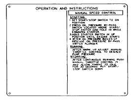
a.
Instruction plate. Mounted on the throttle panel
on the control panel assembly. It displays operating
instructions for starting, running, and stopping the
centrifugal pump unit.
1-4
|