|
| |
TM 5-4320-305-24
2-18. REPLACE/REPAIR SUCTION ASSEMBLY, STRAINER ASSEMBLY,
AND GATE VALVE (Continued)
INSTALLATION:
WARNING
Death or serious injury could occur if unauthorized or un-
necessary personnel are in the hoisting area. Permit only per-
sonnel actually engaged in the hoisting operation to be near the
unit and hoisting equipment. All instructions for the hoisting
operations must come from one authorized person. Injury to
personnel or damage to equipment could occur from improper
hoisting. Hoist the load slowly to avoid tearing out lifting bail
assembly, slipping slings, or load shift. Do not jerk the load or
swing it from side-to-side when hoisting. This places additional
stress on hoisting components which can cause failure and loss of
load. Be sure hoisting equipment is on solid footing and is
suitable for the size of the load. Watch boom angle and overhead
clearance when hoisting.
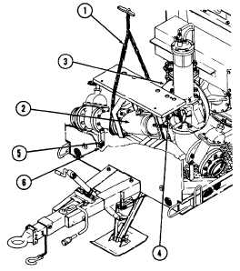
1 Position a suitable lifting device (1) equipped with a
spreader bar and slings over suction assembly (2).
2 Attach slings around assembly and put tension on
slings. Make sure assembly is properly supported.
Spread slings on spreader bar so that slings hang
vertically when attached to assembly.
3 Lift suction assembly (2) and remove from blocks on
work platform. Lower carefully so that suction
assembly (2) alines with pump body (3). Aline holes
in strainer body with studs on pump body. When
these holes and studs are alined, slide suction
assembly (2) toward pump body (3) so that flanges
mate and engage properly.
4 Install nuts and lockwashers (4) on pump body studs.
Do not tighten hex nuts.
5 Install bolts (5) and nuts and lockwashers (6) on trailer
frame. Do not tighten bolts.
6 Tighten nuts (4) alternately until secure. Tighten bolts
(5) securely in a cross pattern.
2-75
|