|
| |
TM 5-4320-305-24
4-13. REPLACE/REPAIR CRANKCASE ASSEMBLY (Continued)
4
Measure camshaft bearing journal diameter and determine radial clearance in accordance with paragraph 4-8. If
radial clearance is not within tolerance limits, replace bushing or camshaft to bring radial clearance within tolerance
limits.
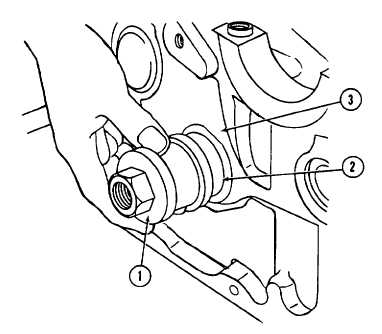
5
Install camshaft bearing tool No. 143630 (1) and remove camshaft bushing (2) from crankcase (3).
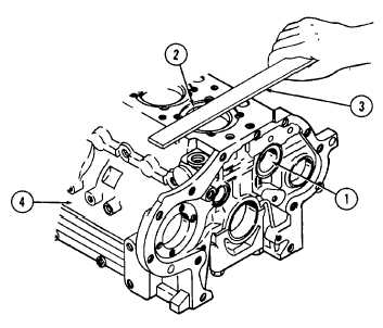
6
Measure camshaft bushing bore (1) in crankcase
with micrometer. Measurement should be 2.0461 to
2.0484 inches (51.97 to 52.030 mm). If
measurement is not within these tolerance limits,
crankcase must be replaced.
7
Inspect cylinder seats (2). Make sure they are
smooth and flat. Use a steel straightedge (3) to
check flatness. If seats are damaged beyond repair,
replace crankcase (4). If seats can be ground
smooth or have minor nicks or burrs, repair in
accordance with REPAIR instructions.
4-107
|