|
| |
TM 5-4320-305-24
4-10. REPLACE/REPAIR PISTON ASSEMBLY (Continued)
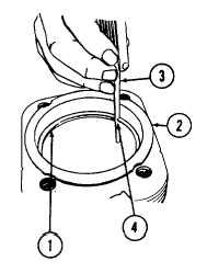
15 Measure piston ring gap.
a. Use piston to push piston rings (1), one at a time, down into
cylinder (2). With feeler gage (3), measure ring gap (4)
according to the following chart.
NOTE
Push ring in far enough to be in the normal area of ring
travel, about 1.18 to 1.57 inches (30 to 40 mm).
NORMAL RING
RING GAP
GAP
WEAR LIMIT
inches
inches
PISTON RING
(millimeters)
(millimeters)
Compression
0.0138 to 0.0217
0.1575
rings
(0.35 to 0.55)
(4.00)
Oil control
0.0008 to 0.0157
0.0984
ring
(0.25 to 0.40)
(2.50)
b. If compression ring gap (4) measurements are less than 0.0138 inch (0.35 mm), the gap may be widened by
very carefully filing or stoning. See REPAIR step 2 for details.
c. If the double-chamfered oil control ring gap measurement is less than 0.0098 inch (0.25 mm), replace the
double-chamfered ring.
d. If any ring gap measurement is greater than 0.1575 inch (4.0 mm), replace the piston ring set.
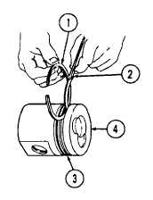
16 Measure piston ring side clearance.
a. Measure piston ring (1) side clearance with new piston rings
only. Measure side clearance of each piston ring with feeler
gage (2) in its corresponding piston ring groove (3) in
accordance with the following chart.
4-78
|