|
| |
TM 5-4320-305-24
44. REPAIR INJECTION PUMP (Continued)
d. Install spring (71) and filler (70).
e. Install a new sealing ring (69).
f. Install pipe connection (68) using torque wrench. Torque to 32 to 33 ft-lb (43.4 to 44.8 N.m).
g. Repeat steps a through f for remaining five bores.
6
Apply thread compound to threads of screw plug (76). Install screw plug into housing.
7
Apply thread compound to screw plug (53). Install screw plug into housing using plug tool KDEP 2993 and torque
wrench. Torque to 44 to 50 ft-lb (59.7 to 67.8 N.m).
8
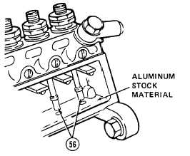
Place pistons (56) into bores as tagged during disassembly. Using plunger pliers KDEP 2915, install the piston over
plunger (74) so that markings on piston face outward.
9
Cut a piece of aluminum stock to size to fit ledge of housing.
Place the cut aluminum stock on ledge to hold piston in
position as shown.
WARNING
Death or serious injury could occur if compressed air is directed against the skin.
Do not use compressed air for cleaning or drying unless the pressure is/has been
reduced to 30 psi (2.11 kgcm2 ) or less. When working with compressed air
always use chip guards, eye protection, and other personal protective equipment.
10 Install a 1/4-28 pipe plug into threaded port near drive end of housing. Connect a source of compressed air to the
threaded port near the governor end of the housing using a 1/4-28 connector.
11 Immerse the housing into a vat of clean calibrating fluid. Apply 40 psi (2.81 kgcm2) air pressure to the housing.
Inspect for defects as follows:
a. Check for air bubbles from screw plugs (76 and 53). Air bubbles indicate defective parts.
b. Check for air bubbles from around delivery valve (73) and barrel seats of housing. A steady stream of air bubbles
indicates a defective sealing ring (69) or sealing washer (72). An intermittent stream of air bubbles is
permissible.
4-19
|