Order this information in Print

Order this information on CD-ROM

Download in PDF Format


Click here to make tpub.com your Home Page

Page Title: REPLACE ENGINE ASSEMBLY (Continued)
Back | Up | Next

Click here for a printable version

Google


Web
www.tpub.com

Home


Information Categories
.... Administration
Advancement
Aerographer
Automotive
Aviation
Combat
Construction
Diving
Draftsman
Engineering
Electronics
Food and Cooking
Math
Medical
Music
Nuclear Fundamentals
Photography
Religion
USMC
   
Products
  Educational CD-ROM's
Printed Manuals
Downloadable Books


TM 5-4320-305-24 3-6. REPLACE ENGINE ASSEMBLY (Con tinued) 4 
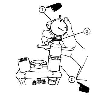
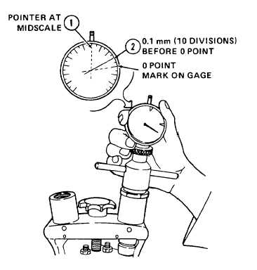
Install dial gage No. 100400 (1).  Pretension gage to midscale (approximately 5.0 mm) on adjusting  device  No.  100640  (2).    Secure  in place using knurled nut (3). 5 Slowly   rotate   V-belt   pulley   clockwise   until piston starts to push valve up.  Gage pointer (1)  will  move  clockwise.    Continue  to  rotate V-belt pulley until gage pointer stops.  This is Top Dead Center (TDC). 6 Stop rotation at TDC, and mark V-belt pulley at  this  location.    Location  should  align  with roll pin in front cover above pulley.  Remove adjusting  device  No.  100640.    Repeat  steps 2  through  6,  if  necessary.    Replace  valve covers on cylinders 1 and 2. All data on Pages 3-28 and 3-29 deleted. Change 1 3-27

Privacy Statement - Press Release - Copyright Information. - Contact Us - Support Integrated Publishing

Integrated Publishing, Inc. - A (SDVOSB) Service Disabled Veteran Owned Small Business