Order this information in Print

Order this information on CD-ROM

Download in PDF Format


Click here to make tpub.com your Home Page

Page Title: REPLACE ENGINE ASSEMBLY (Continued)
Back | Up | Next

Click here for a printable version

Google


Web
www.tpub.com

Home


Information Categories
.... Administration
Advancement
Aerographer
Automotive
Aviation
Combat
Construction
Diving
Draftsman
Engineering
Electronics
Food and Cooking
Math
Medical
Music
Nuclear Fundamentals
Photography
Religion
USMC
   
Products
  Educational CD-ROM's
Printed Manuals
Downloadable Books


TM 5-4320-305-24 3-6.  REPLACE ENGINE ASSEMBLY (Continued) 2 
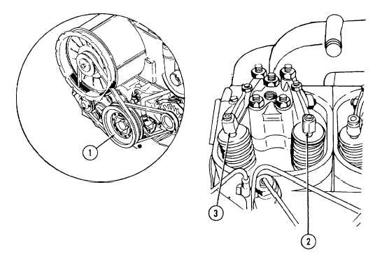
Rotate crankshaft by rotating crankshaft V-belt pulley (1) clockwise until valves are in the overlap position on cylinder number one. The exhaust valve (2) should be closing and its valve stem rising. The inlet valve (3) should be opening and its valve stem going down. Rotate crankshaft another one-half revolution or 180 degrees of clockwise rotation of the V-belt pulley. 3 
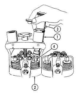
Mount  adjusting  device  No.  100640  (1)  on  cylinder head  assembly  (2).  Locate  pressure  screw  (3)  over exhaust valve and, turn pressure screw counterclockwise until it contacts valve end of rocker arm.  Continue  rotation  for  six  more  revolutions  to compress valve spring (4) to the necessary 5.0 mm to 6.0 mm. 3-26    Change 4

Privacy Statement - Press Release - Copyright Information. - Contact Us - Support Integrated Publishing

Integrated Publishing, Inc. - A (SDVOSB) Service Disabled Veteran Owned Small Business