|
| |
TM 5-4320-305-24
2-24. REPLACE/REPAIR THROTTLE ACTUATOR, QUICK RELEASE LINK, AND MAGNETIC
PICKUP (Continued)
ADJUSTMENT:
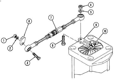
1 Remove nut (1), washer (2), and bolt (3).
2 Remove nut (4), washer (5), bolt (6), and quick release link (7).
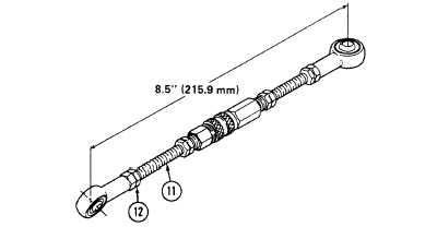
3 Measure distance between the two rod end bores of quick release link. The distance should be 8.5 inches (216.9 mm).
If necessary, adjust the distance by loosening locking nut (1) at either end, and threading rod (11) in or out of the rod
end bore as needed. Secure locking nut (12).
4 Install bolt (3) through front end of quick release link (7) and injector throttle lever (8). Install washer (2) and nut (1)
onto bolt (3).
5 Push injector throttle lever (8) to lowest speed position, full forward toward pump body.
6 On the control panel, set the MODE SELECT switch to MANUAL and set the SET POINT switch to ON at the lowest
setting in the start range. The actuator arm (9) will rotate to the lowest speed position.
2-100
|