|
| |
TM 5-4320-305-10
2-6.
OPERATING PROCEDURE (Continued)
Impeller cavitation occurs when engine speed is increased beyond the point of maximum suction
vacuum. Cavitation is harmful to the pump unit and should be avoided at all times. Cavitation is
indicated by a loud cracking noise in the pump housing.
NOTE
Engine speed and pump discharge will vary in accordance with the output demand and the physical
layout of the system. When there is no increase in vacuum (suction) as indicated on the suction gage,
maximum pumping capacity has been reached.
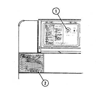
g.
Adjustments. Engine speed and pump
discharge pressure are controlled with SET POINT
switch (1). Turn SET POINT switch clockwise to
increase engine speed and pump discharge pressure,
counterclockwise to decrease engine speed and pump
discharge pressure.
(1)
Engine speed. Engine speed required
to drive the pump varies with the weight of the liquid
being pumped and the rate of pumping. See pump
performance data plate (2), located on the noise shield,
to determine the correct flow rate for the liquid being
pumped. Pump capacities are shown in US gallons per
minute (cubic meters per hour). Discharge pressures
are shown in psi and feet of head for 1.00, 0.72, and
0.85 specific gravity liquids. Engine speed is shown in
100 rpm increments from 2000 to 2400 rpm (maximum
governed speed). Pump and engine assembly will give
satisfactory life and performance when operated in
accordance with the pump performance data.
(2)
Discharge pressure adjustment. The discharge pressure required varies according to the demands of
the pumping system or application. Adjust SET POINT switch (1) and observe the suction and pressure gages (2 and 3).
When the discharge pressure reading stabilizes, compare it to the required discharge pressure. Readjust the SET
POINT switch until the required discharge pressure is set. Once the discharge pressure is set, the automatic pressure
control (control box) will adjust the engine speed to maintain the discharge pressure.
h.
Stopping. Instructions (4) for stopping operation are on the control panel assembly. Follow these stopping
procedures.
(1)
Turn SET POINT switch to START RANGE. This gradually cools the pump before shutdown. In a
multi-pump system with recirculating or bypass lines, the load may be switched to these lines during
shutdown of an individual pump.
(2)
Turn MODE SELECT switch (5) to MANUAL position.
2-73
|