|
| |
TM 5-4320-305-10
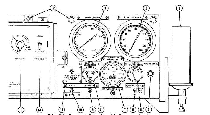
Table 2-1. Operator’s Controls and Indicators - Continued
KEY
CONNECTOR
FUNCTION
3
Ether start kit
Used to help start engine when the air temperature is
too cold for normal start. Operated by a control knob
on bottom of ether cylinder. Mounted on right side of
control panel housing.
4
ALTERNATOR light
Lights when battery is charging. It may light briefly
after starting the engine, and should go out with continued
operation.
5
ENGINE OIL PRESSURE gage
Indicates engine oil pressure in psi. Electrically connected
by a wire to the engine. Graduated in 30 psi
(206.7 kPa) increments from 0 to 120 psi (0 to
826.8 kPa).
6
PANEL LIGHTS switch
Switch used to turn panel lights on and off. Push
switch up for bright light, down for dim light.
7
TACHOMETER/HOURMETER
Indicates engine speed in revolutions per minute (rpm)
gageand maintains a running total of engine operating
hours to tenths of an hour. Graduated in 500 rpm
increments from 0 to 4000 rpm. Time meter will record
up to 9999.9 hours of operation.
8
BATTERY VOLTMETER
Indicates battery voltage.
gage
2-2
|