|
| |
TM 5-4320-305-10
2-15.
EMERGENCY PROCEDURES (Continued)
After centrifugal pump unit is primed and pumping, maintain engine idle speed until engine
warm-up cycle is complete.
(10) Run the centrifugal pump unit with engine at idle speed for a few minutes. Adjust MANUAL
THROTTLE CONTROL knob until desired operating speed is reached. Refer to paragraph c.
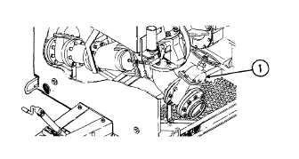
(11) Partially close the discharge gate
valve (1) to fill the hose slowly and
guard
against
excessive
shock
pressure to fittings. As the discharge
hose fills, open the discharge gate
valve until it is adjusted to the
required discharge flow rate.
Impeller cavitation occurs when engine speed is increased beyond the point of maximum suction
vacuum. Cavitation is harmful to the pump unit and should be avoided at all times. Cavitation
can be detected by a very loud cracking noise in the pump housing.
NOTE
Engine speed and pump discharge will vary in accordance with the output demand and the
physical layout of the system. When there is no increase in vacuum (suction) as indicated on the
suction gage, maximum pumping capacity has been reached.
d.
Adjustments. Engine speed and pump discharge pressure are controlled with the MANUAL THROTTLE
CONTROL knob (1). Press button in center of MANUAL THROTTLE CONTROL knob and pull out to increase engine
speed and pump discharge pressure; push in to decrease engine speed and pump discharge pressure. Adjust the
MANUAL THROTTLE CONTROL until the required speed and discharge pressure are reached. Engine speed and pump
discharge pressure vary with the weight of the liquid being pumped and the demands of the pumping application. See
the pump performance data plate, located on the noise shield, to determine the correct flow rate for the liquid being
pumped. Pump capacities are shown in US gallons per minute (cubic meters per hour). Discharge pressures are shown
in 2-86psi and feet of head for 1.000, 0.72, and 0.85 specific gravity liquids. Engine speed is shown in 100 rpm
increments from 2000 to 2400 rpm (maximum governed speed). Pump and engine assembly will give satisfactory life
and performance when operated in accordance with the pump performance data.
2-86
|