Order this information in Print

Order this information on CD-ROM

Download in PDF Format


Click here to make tpub.com your Home Page

Page Title: CHAPTER 2 OPERATING INSTRUCTIONS
Back | Up | Next

Click here for a printable version

Google


Web
www.tpub.com

Home


Information Categories
.... Administration
Advancement
Aerographer
Automotive
Aviation
Combat
Construction
Diving
Draftsman
Engineering
Electronics
Food and Cooking
Math
Medical
Music
Nuclear Fundamentals
Photography
Religion
USMC
   
Products
  Educational CD-ROM's
Printed Manuals
Downloadable Books


TM   5-4320-304-14 TM   08922A-14/1 CHAPTER  2 OPERATING   INSTRUCTIONS Section  I.  DESCRIPTION  AND  USE  OF  OPERATOR’S  CONTROLS AND   INDICATORS WARNING Personal  injury  may  result  if  the  engine  is  not  turned  off during  service  or  maintenance. 
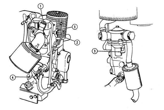
Table 2-1. Operator’s Controls and Indicators Key 1 Control  or  Indicator Restriction  indicator 2 Throttle   control   hand   lever Function Indicates  blockage  of  air  filter.  A  red  band  appears  in window  to  indicate  the  need  for  cleaning  or  replacement. Indicator  is  threaded  into  air  cleaner  adapter,  and  is actuated by high negative pressure. Indicator can be reset. Controls  engine  speed.  With  the  hand  lever  in  START position,  the  engine  is  at  highest  operating  speed.  By moving  the  lever  between  START  and  STOP,  the  de- sired engine speed can be obtained. 2-1

Privacy Statement - Press Release - Copyright Information. - Contact Us - Support Integrated Publishing

Integrated Publishing, Inc. - A (SDVOSB) Service Disabled Veteran Owned Small Business