|
| |
TM 5-4320-304-14
TM 08922A-14/1
1
2
6-3. REPAIR/REPLACE CONNECTING ROD (Continued)
INSPECTION:
3
4
5
6
Dry cleaning solvent P-D-680 (safety or Stoddard’s Solvent)
is potentially dangerous. Avoid repeated and prolonged
breathing of vapors and skin contact with the liquid. Do
not use near open flame, arcing equipment, or other ignition
sources. Always wear eye protection and protective cloth-
ing. The flash point of P-D-680 is 100° to 138°F (38° to
59°C).
Death or serious injury could occur if compressed air is
directed against the skin. Do not use compressed air for
cleaning or drying unless the pressure is/has been reduced
to 30 psi (2.06 bar) or less. When working with com-
pressed air, always use chip guards, eye protection, and
other personal protective equipment.
Clean connecting rod components with dry cleaning solvent. Remove any carbon deposits with a
wire brush. Clean inside surface of rod bushing (9), both connecting rod halves (6 and 7), and
bearing (8). Blow compressed air through the drilled oil passage in connecting rod to clean con-
necting rod and rod bushing.
Visually inspect connecting rod for bending,
warping, cracking, rust, or other damage. Check
for cracks using MIL-I-6868 magnetic particle
inspection. Replace if twisted or bent. Grind
or replace if indications of cracks are revealed
by magnetic particle inspection.
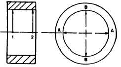
Measure and record rod bushing (9) inside
diameter. Measure at points 1 and 2 along
axes A and B. Measurements should be 0.9951 to 0.9858 inch (25.225 to 25.040 mm). If any
measurement is outside these limits, replace rod bushing.
Inspect upper and lower bearing halves (8) for excessive wear, scoring, pitting, flaking, etching,
and signs of overheating. Inspect bearing backs for bright spots (bearing moving in supports).
Temporarily assemble connecting rod with two new Allen screws and without bearings. Using a
torque wrench, tighten screws to 29.50 foot pounds (40 N·m). Apply some oil to threads and
contact surfaces.
Measure inside diameter of connecting rod, bearing bore. Measurement should be 1.8114 to
1.8107 inches (46.010 to 45.994 mm). If measurement is outside specified limits, replace
connecting rod.
6-7
|