 |
|||
|
|
|||
|
Page Title:
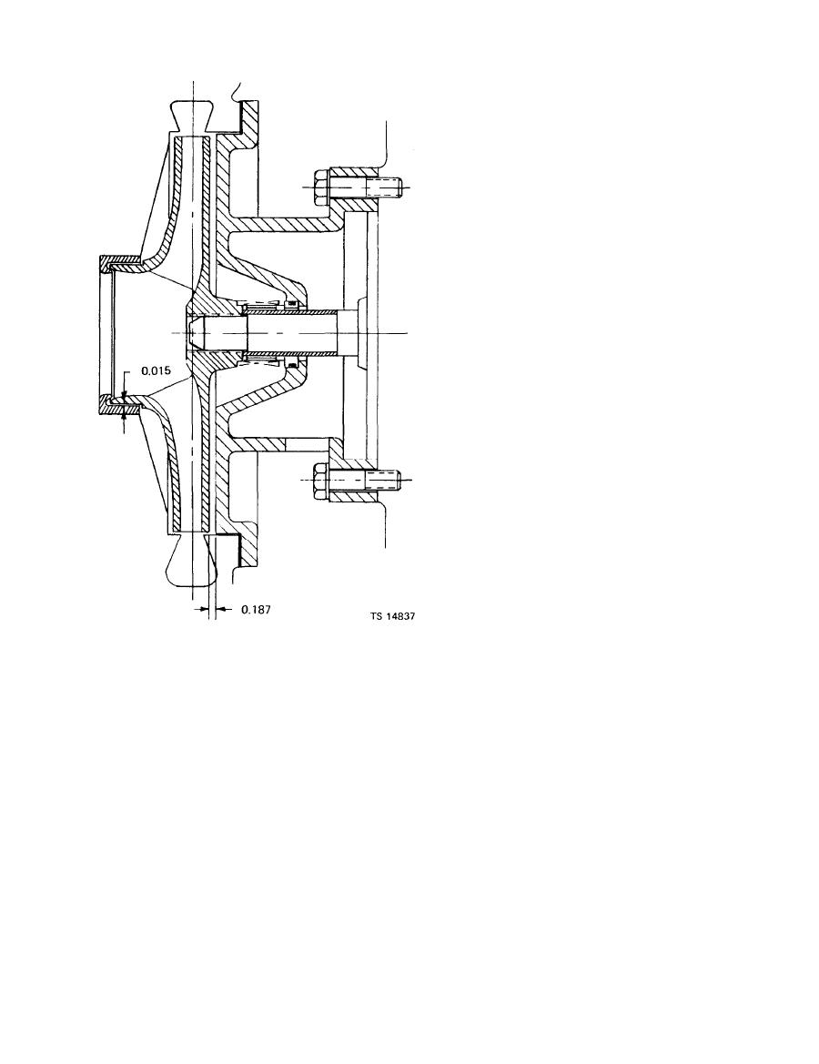
Figure 7-2. Pump tolerances and wear limits. |
|
||
| ||||||||||
|
|
 TM 5-4320-273-14
b. Disassembly.
(1) Remove impeller (24) by inserting a rod into
each side of impeller. Remove flywheel screen from
engine and hold crankshaft with a pipe wrench. Im-
peller can now be loosened by turning coun-
terclockwise. If impeller cannot be loosened by hand
tap rods with a plastic hammer.
(2) Remove the shaft sleeve (25) and seal (26).
Retain the shims as a set. You will want to reinsert
the same shim thickness at reassembly unless related
parts are replaced.
(3) Remove the screws (27 and 28) and lock-
washers (13), and remove the intermediate bracket
(23).
(4) You should not remove the studs (29, 30, and
31) from the pump casing unless they are damaged
and require replacement.
c. Cleaning and Inspection.
(1) You should replace the pump seal (26) at each
overhaul. Always replace the complete seal assembly,
not individual parts.
WARNING
DRY CLEANING SOLVENT, P-D-680
or P-S 661, used to clean parts is
potentially dangerous to personnel
and property. Avoid repeated and
prolonged skin contact. DO NOT use
near open flame or excessive heat.
Flash point of solvent is 100 to 138F
(38 to 60C).
(2) Clean all remaining parts with cleaning
solvent (fed. spec. P-D-680); dry thoroughly.
(3) Inspect the impeller (24) for cracks, wear,
broken vanes, chips, distortion, and damaged threads.
(4) Inspect the wear ring (32) in the pump casing
Figure 7-2. Pump tolerances and wear limits.
for wear, cracks, and other damage. If the inspection
indicates wear or damage, you must replace the wear
ring.
(4) Remove the nuts (2), washers (3 and 4), and
(5) Inspect the pump casing for cracks, distor-
screws (5) that secure the lifting bail (6) and support
(7) to the discharge elbow (8).
tion, damaged threads, or other damage. If studs are
damaged, replace them.
(5) Remove the nuts (9) and lockwasher (10) and
(6) Inspect the intermediate bracket (23) for
remove discharge elbow (8) and gasket (11).
(6) Remove the nuts (12), lockwashers (13), and
cracks, distortion, scoring, and other damage; replace
screws (14) securing the base of the pump casing (15)
a damaged intermediate bracket.
(7) Inspect the O.P.W. fitting (16, 17, and 18) for
to the frame.
cracks, damaged threads, distortion, or other damage.
(7) Remove O.P.W. dust cap (16), gasket (17), and
Replace damaged parts. Always replace gasket (17).
adapter (18) from pump casing.
(8) Inspect cleanout cover (19) for cracks, distor-
(8) Remove the nuts (2) and washers (3) that
tion, or other damage. Replace if damaged. Always
secure the cleanout cover (19) and gasket (20) to the
replace gasket (20).
pump casing (15).
(9) Remove the nuts (21) and lockwashers (22)
d. Reassembly and Installation.
(1) Install the wear ring (32) if
you had removed
that secure the intermediate bracket (23) and the
it.
pump casing (15).
(2) Coat the stationary members of the pump
(10) Insert hook of a hoist device into discharge
seal (26) sparingly with light engine oil. Install the
of pump casing (15) and slide pump away from the
stationary seal parts in the bore of the intermediate
engine, Remove from frame.
|
|
Privacy Statement - Press Release - Copyright Information. - Contact Us |
