 |
|||
|
|
|||
|
|
|||
| ||||||||||
|
|
 TM 5-4320-273-14
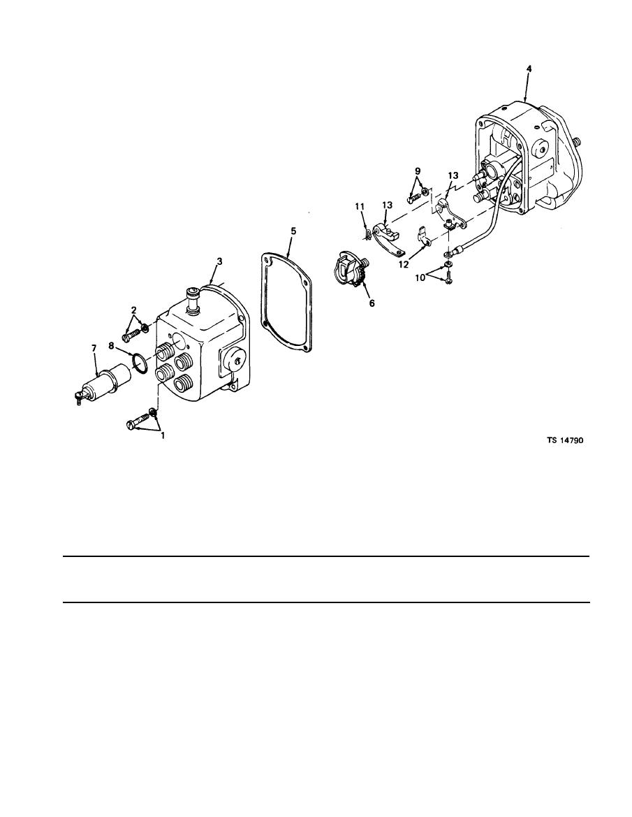
8. Preformed packing
1. Screw, assembled washer
9. Screw, assembled washer
2. Screw, assembled washer
10. Screw, assembled washer
3. End cap assembly
11. Retaining ring
4. Housing assembly
5. Gasket
12. Cam wick
13. Breaker point assembly
6. Distributor rotor
7. Capacitor
Figure 4-.5. Magneto.
Table 4-2. Troubleshooting -- Continued
MALFUNCTION
TEST OR INSPECTION
CORRECTIVE ACTION
ENGINE -- Continued
Remove end cap assembly (3). Remove and discard end cap gasket (5).
Remove distributor rotor (6).
Use a feeler gage to check breaker point gap after rotating the crankshaft with handcrank until points are
wide open. Gap should be 0.015 inch (0.03 cm).
Resurface burnt or pitted points with small tungsten file. Badly worked or pitted points must be replaced as
follows:
Disconnect ground switch lead from the capacitor (7). Remove the capacitor and preformed packing (8) from
the end cap assembly. Discard both the capacitor and preformed packing.
Remove screws and assembled washers (9 and 10) and retaining ring (11) that secure the breaker point
assembly and cam wick (12) to the bearing support. Remove breaker point assembly (13) and discard.
Install serviceable breaker point assembly (13) and cam wick (12) on bearing support using screws and
assembled washers (9) and retaining ring (11).
Leave screws loose enough to permit adjustment.
|
|
Privacy Statement - Press Release - Copyright Information. - Contact Us |
